
Overview
A piezoelectric element (also known simply as a piezo or piezo bender)—by itself, without a case or tuned enclosure—has a very low sound pressure level (SPL). This is mostly due to cancelation that occurs when the face of a sound producing device (which creates positive air pressure) is able to interact with the back of the sound producing device (which creates negative air pressure); the same as what happens when evaluating a speaker that is not properly mounted in an enclosure.
By mounting a piezo into an enclosure, that cancelation is mitigated. Furthermore, by tuning the enclosure to a frequency that aligns with the piezo's resonant frequency, a Helmholtz chamber is created. Within a Helmholtz chamber a larger volume of air becomes a piston that moves air, more efficiently than the piezo by itself, by more closely matching the acoustic impedance of air.
Mounting the Piezo in a Helmholtz Chamber
The method of mounting the piezo, within the Helmholtz chamber, influences the resonant frequency, impedance, bandwidth and resulting sound pressure level of the whole device.
Nodal Mount
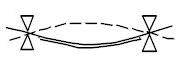
Mounting a piezo at its nodal point—just outside the diameter of the ceramic disc—results in the highest SPL at the expense of reduced bandwidth (overall frequency response). This mounting method takes advantage of the resonant frequency of the ceramic disc and narrow impedance peak. Choose this mounting method when using a piezo to create a single tone.
Edge Mount
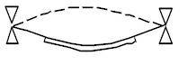
Mounting a piezo at the outer edge of its metal plate results in the widest usable bandwidth (overall frequency response). This mounting method distributes the impedance peak over a wider range and increases the moving surface area of the piezo, at the expense of peak SPL. Choose this mounting method when using a piezo to create tones at multiple frequencies.
Helmholtz Resonating Chamber Design
The highest SPL is obtained when the piezo excites a resonator with a resonant frequency equal to, just below, or one octave lower, the resonant frequency of the piezo regardless of the mounting method chosen.
If using a piezo to create multiple frequencies with an edge mount design, set the chamber tuning frequency to (or just below) the lowest frequency to be reproduced. If using a piezo to create a single tone, set the chamber tuning frequency to just below the frequency.
The following equation can be used to design a Helmholtz Resonator:
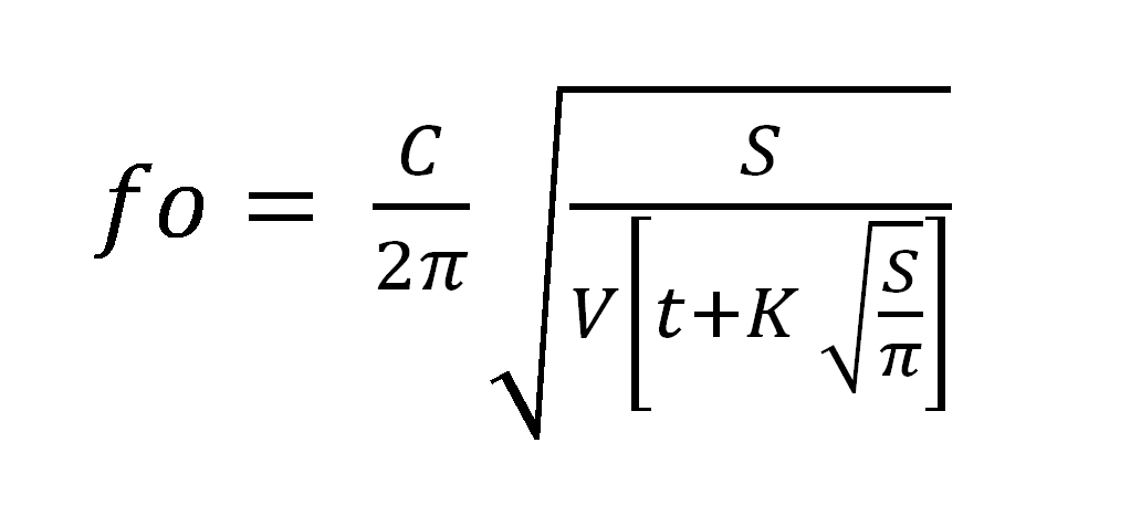
Where:
fo = Resonant frequency of Helmholtz cavity in Hertz (Hz)
C = Speed of sound in air contant: 343 meters/second @ 20°C
t = Sound emitting hole length in meters
K = Magnitude of equilibrium constant: 1.5
V = Cavity volume in square meters and is calculated using:
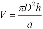
Where:
h = Cavity height in meters
D = Cavity diameter (diameter of the mounting circle) in meters
a = 4
S = Surface area of sound emitting hole(s) in square meters and is calculated using: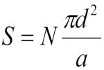
Where:
N = Number of sound emitting holes
d = Sound emitting hole diameter in meters
a = 4
Recommended Helmholtz Chamber Design
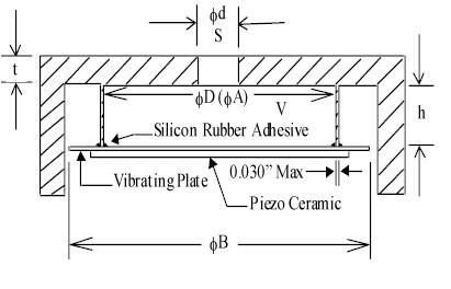
Cavity dimensions are determined by the calculations above with the following notes
1. For nodal mount, ∅D should be set equal to the bender nodal diameter ∅A.
2. For edge mount, ∅D should be set equal to ∅B, less 1 millimeter (0.001 meter).
The following assumptions are made:
- The resonator cavity and sound emitting hole dimensions are much smaller than the wavelength of sound at the frequency of interest (f), where wavelength in meters = f/343.
- That the sound emitting hole is cylindrical in geometric shape.
- That where multiple sound emitting holes are used, all holes are cylindrical in geometric shape, all holes have equal diameters, and all holes have equal length.
- That where multiple sound emitting holes are used, the term (t) representing their length in the above equation, shall represent a single common non-accumulative length.
- That the bender bonding adhesive is elastic such as a silicone rubber (RTV) and consists of a full annular ring.
- That the case material is sufficiently rigid enough to prevent flexure due to bender motion.
Basic Drive Circuits for Piezos and Piezo Transducer
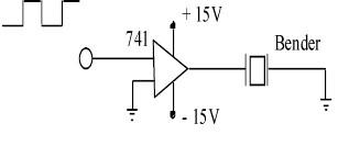
The following circuits illustrate how only a few low cost electronic components are required to drive piezos and piezo transducers (piezo mounted in a tuned Helmholtz chamber). All piezos are compatible with either CMOS or TTL integrated circuits tied to an IC to control voltage. For highest SPL, a push-pull circuit is recommended, as is driving the piezo at its resonant frequency or sweep through frequencies that contain the piezo's resonant frequency.
Op AMP or Comparator Drive Circuit Driven by CMOS or TTL Logic
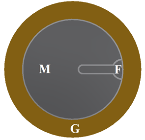
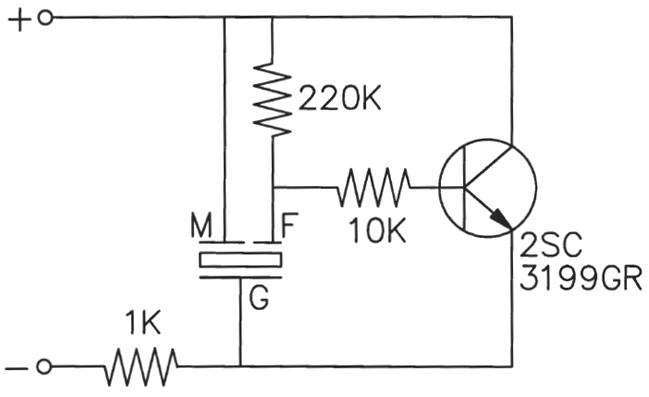
Piezo with Feedback Circuit for Tone Generation
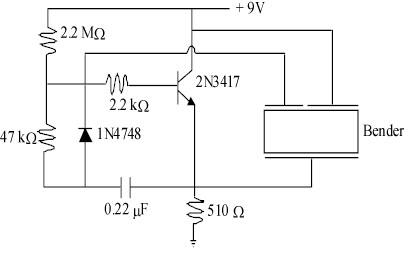
A piezo bender’s ceramic disc can be configured with or without a feedback circuit. Piezo benders not only flex when given an input voltage, they also generate an output voltage when flexed.
Adding a feedback circuit to a piezo bender allows it to be used in conjunction with an external transistor and DC voltage to create a low-cost oscillation circuit.
The oscillation circuit generates a tone based on the resonant frequency of the piezo bender, which is the frequency at which the piezo bender creates the most output. This results in a higher sound pressure level (SPL) and lower frequency drift.
Low Cost Pulsing Circuit
Designed for minimum part count, this pulsing circuit will oscillate at resonance. The sound produced is more suitable for an alarm application and the rate of pulsing can be varied by charging the RC time constant.