

Frequently Asked Questions
-
Does PUI Audio use any of the chemical substances listed in the European Union's REACH (Registration, Evaluation, Authorization and Restriction of Chemicals) list?
With the increasing concerns of hazardous substances in our environment, we would like to inform you that our products do not contain any of the chemical substances listed below per the European Union's REACH Substance of Very High Concern (SVHC) candidate list.
-
Does PUI comply with the RoHS requirements?
After the European Union passed the “Restriction of the use of certain hazardous substances in electrical and electronic equipment”, commonly known as “RoHS”, PUI Audio has worked diligently to comply with the RoHS requirements.
-
How does PUI Audio's part numbering system work?
PUI Audio has adopted a "Smart Part Numbering System" that includes the device's parameters. This allows you to identify the device type, size, voltage, frequency and so on just by reviewing the part number.
Note: The “Smart Part Numbering System” does not apply to all parts.
-
Our Product Availability Statement
-
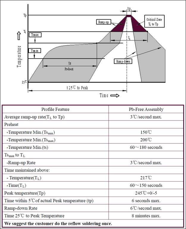
Reflow Solder Profile for Surface Mount Devices
-
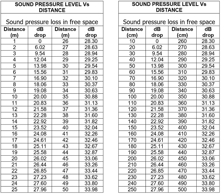
SPL Damping by Distance
-
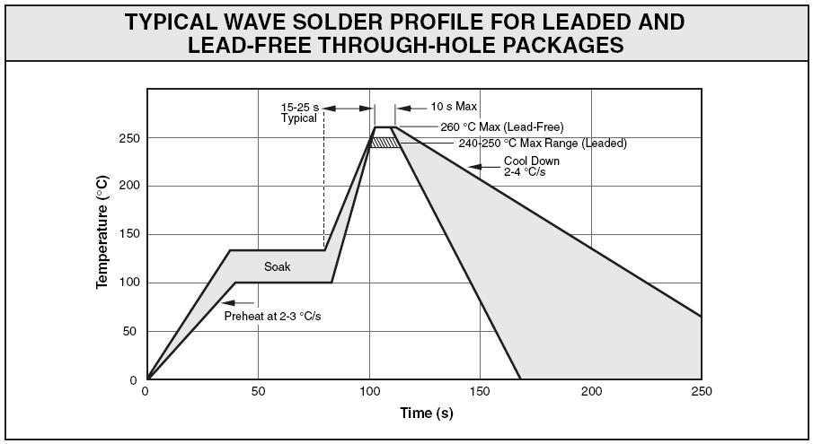
Wave Solder Profile
-
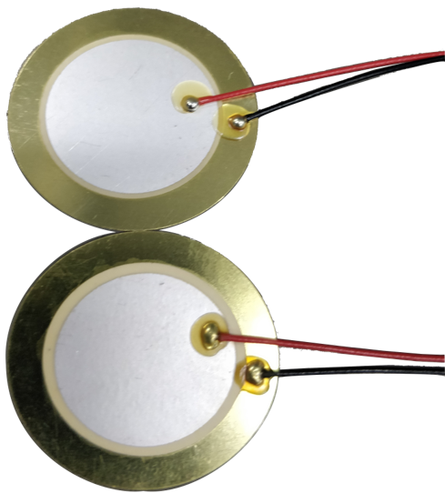
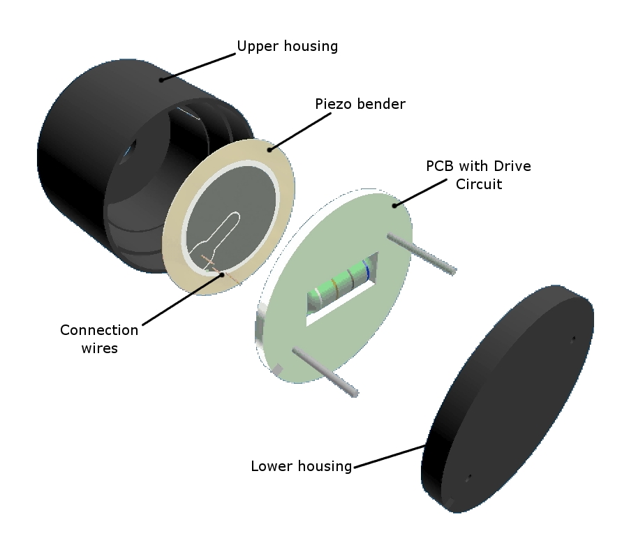
How are piezo benders constructed?
-
How do you solder wires onto piezo benders?
Soldering Wire to Piezo Benders
Equipment required:
- Temperature controlled soldering iron
- PbSn or Pb Free solder 0.020" (0.5 mm) diameter rosin core solder
- Kester 1544 flux or equivalent
- 28 to 32 AWG stranded wire
- Isopropyl alcohol
Soldering Procedure:
Pre heat soldering iron to 300°C (572°F).
Strip approximately 5/32” (4 mm) of insulation from the wire and tin the lead with solder.
Apply a small pool of liquid flux near the outer edge of the ceramic surface and add small dot of solder with the soldering iron for maximum of 0.5 seconds.
Lay the tinned wire on the solder dot and position the wire for desired orientation.
Apply the soldering iron to the wire, and solder the connection for no more than 0.5 seconds, reflowing solder onto the wire to complete the solder joint. Do not add additional solder unless the wire strands are not adequately covered by solder.
Repeat this procedure for the wire to metal substrate connections including the metal substrate of the bender. Try to keep all connections close together and observe the same lead lay as before.
Clean the flux off all connections with isopropyl alcohol.
Visually examine each joint. The solder connection should be smooth and bright with no cracks or crazing.
Discard the bender if the joint on the ceramic fails by lifting off the silver coating of the bender. DO NOT solder to another spot on the ceramic surface - the performance and life of the bender will be degraded. The metal connection can be resoldered as required. -
What is a feedback circuit on a piezo bender used for?
A piezo bender’s ceramic disc can be configured with or without a feedback circuit. Piezo benders not only flex when given an input voltage, they also generate an output voltage when flexed.
Adding a feedback circuit to a piezo bender allows it to be used in conjunction with an external transistor and DC voltage to create a low-cost oscillation circuit.
The oscillation circuit generates a tone based on the resonant frequency of the piezo bender, which is the frequency at which the piezo bender creates the most output. This results in a higher sound pressure level (SPL) and lower frequency drift. These are signal frequency devices.
-
How are they constructed?
-
What are the mounting options for indicators and sirens?
Surface mount, Thru-hole, Flange mount, Panel mount, Bracket
-
What tones are available?
Continuous, Fast pulse, Slow pulse, Siren, Warble, Chime, Multiple
-
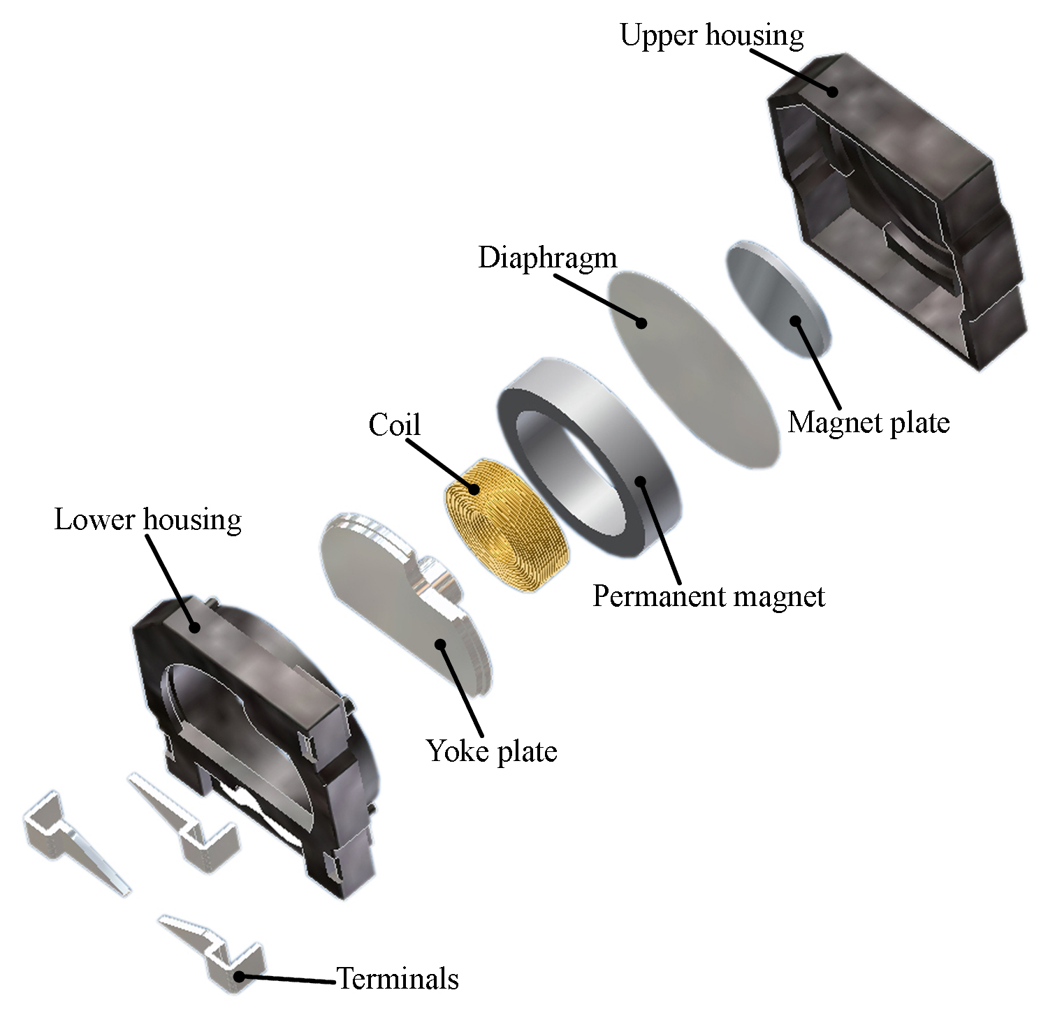
How are transducers constructed?
-
What are the mounting options for transducers?
Surface mount, Thru-hole, Flange mount, Panel mount
-
What is a suggested drive circuit for electromechanical transducers?
-
How do you solder to microphones?
-
What is the difference between omni, uni and noise-canceling microphones?
-
What is the temperature range of PUI Audio microphones?
ECMs: Operating: -20°C ~ +70°C, Storage: -40°C ~ +85°C
MEMS: Operating: -40°C ~ +100°C, Storage: -40°C ~ +125°C
-
What mounting options are available for PUI Audio microphones?
Pin, Solder Pad, Bullseye, Surface Mount
-
How does power and distance effect a speaker's SPL?
-
What cone materials are available?
Paper, Mylar, Cloth, Treated Paper, PEEK, Aluminum
-
What mounting options are available for PUI Audio speakers?
Surface mount, Thru-hole, Flange, Interference Fit